Faking things is at the heart of game development.
The goal isn’t to perfectly simulate reality, but to make something that looks right, feels right, and fits the world
it belongs to. Water is no exception.
There are countless guides on it, stylized ponds, film-ready oceans, each with its own clever tricks. This isn’t meant
to compete with any of them. It’s simply my path: how I pieced together what I already knew with new insights from
scattered resources, and adapted ideas to my world, leaning towards what felt true on screen.
The shader I’ll walk through here started with the simplest of steps: pushing vertices of a mesh up and down to fake
ripples. From there it picked up detail with normal maps, then I went (almost) all in by bending light with refraction,
reflecting the surroundings, and even fakeing a little absorption.
Each version added something new, and each one taught me something.
All of this lives inside Revo Realms, my Three.js playground. What was
meant to be a 3D portfolio, but quickly turned into a space where I test ideas, learn graphics programming, and slowly
stitch together an environment that feels alive.
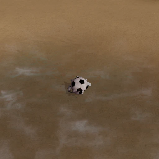
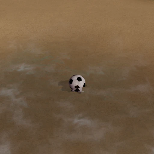
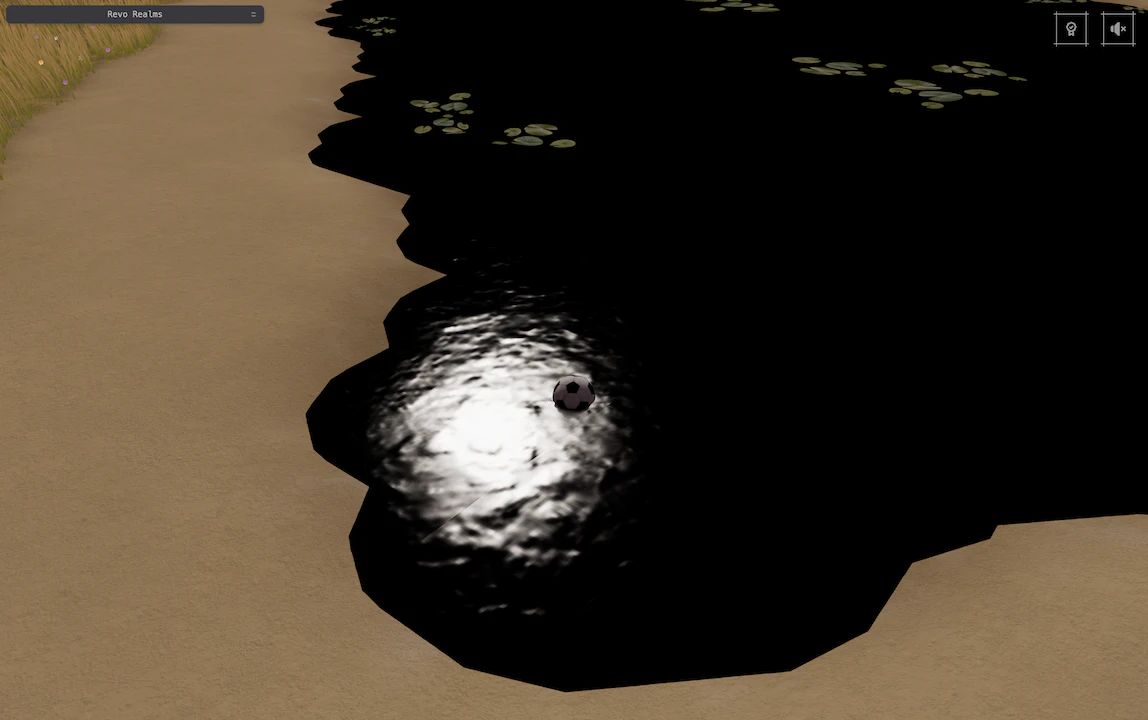
Before diving into the details, here’s the contrast in motion: my first attempt beside the version I have now:
How it startedHow it’s going
The difference is hard to miss.
I’ve always been fascinated by water, in life and in games. It’s an extraordinary substance: essential for survival,
an unstoppable force of nature, yet also deeply calming, whether it falls from the sky in little drops or rests quietly
in the hands of the earth.
Rivers, streams, ponds, oceans, lakes… I had many options when deciding what kind of water Revo should have. At first
I wavered (pun not intended) between a flowing stream and a lake, but in the end I went with the lake.
Almost unconsciously, I shaped it to resemble the small one in Masere Park (see on Google Maps),
located in Pelugo, a small municipality in Northern Italy where I grew up.
And so this story begins, just like my shader did, with a simple first step :)
Chapter I: Displacing vertices
My first attempt started with the most straightforward idea: if you want waves, just move the surface up and down.
That’s the essence of vertex displacement. Conceptually easy to grasp, practically…easy with reservations.
Starting with a flat mesh, each vertex’s height is driven by a combination of sine waves or noise, and if you make
time part of the input, the mesh begins to ripple. Intuitively, the more vertices you have, the smoother the motion
looks, fewer gaps for the GPU to guess between.
This is the easy part. It works, but it is not enough. Even with vertices shifting around, the surface looked strangely
flat.
The culprit? Normals.
What is a normal?
Normals are 3D unit vectors that tell the renderer which way a surface is facing. I had to remind myself of that while
working on this part. Without them, light has no idea how to bounce, so things end up looking flat and dull.
They’re stored per vertex and smoothly interpolated across each triangle (primitive), so each fragment gets an
orientation.
Geometries often come with extra precomputed attributes, normals are one of them. That works fine for static
meshes, but when I started moving vertices around in the shader, the normals didn’t magically auto-update, hence the
flat look.
This is the “with reservations” part: I had to compute and update the normals myself, according to my displacement, for
the lighting to match the new shape.
Not my case, but worth mentioning for the curious: a vertex can be associated with only one normal. This is
problematic when we have sharp edges, like in a cube for example. Duplicating vertices allows each copy to carry its
own normal.
So, normals define how light hits a surface, but what exactly are they shading? The answer is fragments.
I already had a rough idea of what a fragment was, but I owe the clarity I have now to Mike, an interviewer I once
spoke with. He explained it in such a clear and patient way that it stuck.
Allow me to echo his explanation here.
What is a fragment?
Combine a geometry (the shape or structure) with one or more materials (the surface appearance), and you get what’s
called a mesh.
Internally, all geometries are broken down into tiny triangles. When one of those triangles overlaps a pixel on screen,
the rasterizer produces a fragment: a candidate contribution to that pixel’s final color, whose attributes (like UVs
and normals) are interpolated from the triangle’s vertices.
As you can imagine, multiple elements in the scene may overlap:
Several fragments target the same pixel
Here, the same pixel is covered first by the sky, then the ground, then a box, and finally a sphere. Each overlap
generates a fragment, but after depth and blending tests, usually only the nearest opaque one contributes to the final
color.
In a typical 3D pipeline, each mesh goes through a series of stages, some fixed-function, others programmable, where
the programmable ones execute small GPU programs called shaders.
Two of the most common are the vertex shader and the fragment shader (called a pixel shader in DirectX). The vertex
shader determines where each vertex appears on screen, while the fragment shader computes the color of every potential
pixel (called a fragment).
Each fragment then competes in depth and blending tests against other fragments targeting the same pixel. Some survive,
others are discarded, meaning the GPU still did the work even though the result won’t be visible.
Shading fragments that never affect the final image is called overdraw. GPUs reduce it with techniques like
early-Z testing or front-to-back rendering, though with transparency or special blending modes, even hidden
fragments may still contribute.
Shading waves
With a flat mesh, all precomputed normals pointed straight up. Light bounced evenly, and the ripples looked lifeless.
To fix it, I had to recompute normals dynamically. A common trick is the neighbor technique:
Pick two nearby points, slightly offset on X and Z by a small ε.
Raise them using the same displacement function.
Build two direction vectors from the current position to those neighbors.
Cross them, normalize, and you get a new normal pointing outward from the displaced surface.
Be mindful when picking the offset ε: too small and you might get floating-point noise, too large and detail can smear
away. Also, since each neighbor adds more sampling work, whether texture or noise lookups, the cost grows quickly with
vertex count.
When I got it right, the ripples finally caught light. They weren’t perfect, but the surface wasn’t flat anymore.
I agree with Prof. Banner
In my own version, I used a slight variation: instead of elevating three points, I approximated slopes, built
tangent and bitangent vectors, and crossed those. Mathematically it’s equivalent. At the time it felt cleaner since
I only dealt with elevations, but looking back, the three-points method is easier to picture. If I were starting fresh
today, I’d probably choose that.
Outcome
While researching, I came across a fantastic tutorial by Dan Greenheck.
His WebGL take on the neighbor trick looked wonderfully fluid.
My take was simpler: I leaned on a precomputed noise texture (Perlin, Voronoi, Turbulence packed into RGB) instead of
multi-octave procedural noise. It was cheaper at the cost of richness, but good enough.
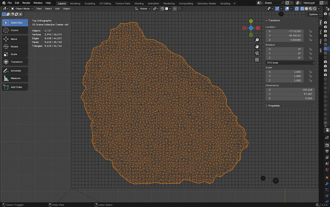
The real limit wasn’t sampling, though, it was geometry. Displacement can only move the vertices that already exist. A
coarse mesh means blocky ripples, no matter how good the math. To mitigate that, I built a custom lake mesh in Blender:
enough subdivisions where water was visible, almost none wasted under terrain.
Custom lake mesh with extra subdivisions where they mattered
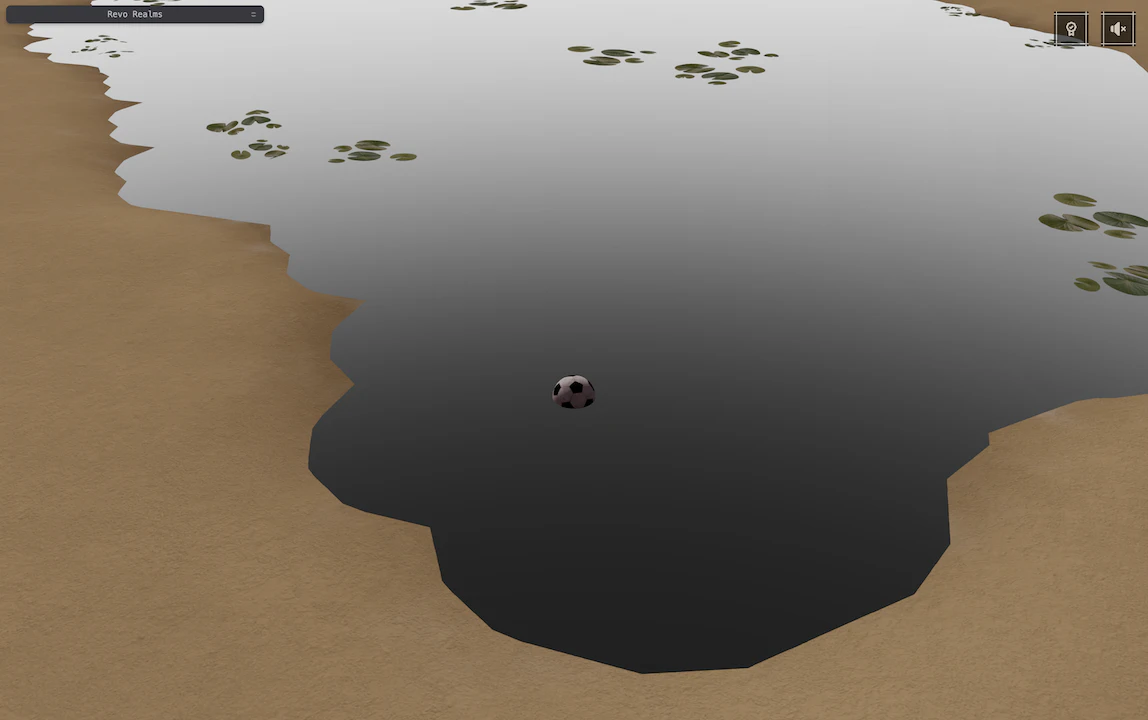
At the very end, I added a touch of environment reflection and Fresnel. Nothing dramatic, but it started to resemble
a nice, cozy lake.
The first attempt: subtle displacement and dynamic normals
It had motion, but still lacked depth. The surface felt repetitive, and the “water-ness” wasn’t quite there.
Still, it was my first real lake in Revo, and it felt like a milestone. Good enough, but I knew I could do better.
Chapter II: Normal textures
A month or so later, determined to improve my first version, I dove back in.
What my first attempt lacked was fine detail. I couldn’t just bump up the vertex count and call it a day, though…that
wouldn’t have been a smart move.
The look of the waves didn’t come from how far vertices moved, silly me, normals dictated how light bounced,
and despite living per vertex they influenced how fragments were shaded.
Then the illumination: if I could have precomputed normals for vertices, why not for fragments too, and skip the
automatic interpolation altogether?
One of those ideas that randomly pops up in the head in the most unusual places.
So I did some research and found that not only that was possible, but it turns out it’s a very common trick in
real-time rendering.
The biggest of brains…
In the previous chapter, I described how I simplified my approach by using a precomputed noise texture to calculate
the elevation for each vertex, then used it to compute the normal which ended up driving the shading.
The idea here is similar, bypass the displacement part and directly get normals from a precomputed texture. In jargon
this specific kind of texture would be a normal map.
By now the word normal should feel familiar. The map part simply means a texture, one of the GPU’s most
fundamental data structures. A texture isn’t just an image, it packs an array of values, along with metadata like format,
dimensions, mipmaps, and filtering, that the GPU interprets however we decide. Sometimes that means colors
(diffuse/albedo), other times directions (normals), heights (displacement), or occlusion. At shader level, all you
really see is a grid of texels waiting to be read.
I kept the same flat mesh and let the fragment shader drive the ripples directly by layering three scrolling normal maps.
The difference was immediate as light scattered and shifted with the ripples without any vertex movement whatsoever.
A short detour: Textures, color spaces, and normal maps
Before going deeper, it’s worth pausing to inspect how normal maps are stored and interpreted. A lot can silently
go wrong here (source: personal experience).
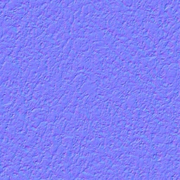
Water normal map
This is what the normal map I used looks like, but to make sense of it, let’s peel back a few layers.
Pixels as vectors
At its core, a pixel is just a vec4(r, g, b, a). In a photo those values mean red, green, blue and alpha a.k.a. color.
In a normal map they represent a direction: vec3(x, y, z). Alpha is often unused.
Since most normals point outward, the blue channel (Z) is bright, while red and green (X and Y) wiggle slightly for
sideways slopes. That’s why normal maps usually look purple, we’re really looking at coordinates disguised as color.
Color spaces
Most everyday textures are in sRGB, which has a gamma curve baked in so they look “right to our eyes”. That’s fine
for photos, but terrible for raw data.
Normal maps must stay in linear color space. If you accidentally sample them as sRGB, the gamma curve will distort
the vectors. The math will still run, but highlights will most likely look muddy and reflections incorrect. It’s one of
those subtle bugs that can waste plenty of time (yep, source is still personal experience…as is the whole article).
Tangent space
Most normal maps are baked in tangent space:
Red → tangent (left/right)
Green → bitangent (up/down)
Blue → normal (outward)
Lighting, however, happens in world or view space. So the tangent-space vector has to be transformed by the TBN
(tangent, bitangent, normal) basis.
On my static flat mesh I could hard-code this basis but for an arbitrary mesh you’d want tangents/bitangents from
geometry (or derivatives), so the normals rotate properly with the surface.
In code:
class WaterMaterial extends MeshBasicNodeMaterial { // ... private sampleTangentNormal = Fn(([uvCoords = vec2(0)]) => { const tex = texture(assetManager.waterNormal, uvCoords); // [0..1] const tangentN = tex.rgb.mul(2).sub(1); // unpack to [-1..1] return tangentN; }); private tangentToObject = Fn(([tangentN = vec3(0)]) => { // hard-coded TBN basis for a flat plane (U → +X, V → −Z, N → +Y) const T = vec3(1, 0, 0); // Tangent const B = vec3(0, 0, -1); // Bitangent const N = vec3(0, 1, 0); // Normal return tangentN.x.mul(T).add(tangentN.y.mul(B)).add(tangentN.z.mul(N)); }); private objectToWorld = Fn(([objectN = vec3(0)]) => { return normalize(modelNormalMatrix.mul(objectN)); }); // ...}
Some normal maps follow DirectX’s convention with the green channel being flipped. If your highlights look inverted,
try negating Y, or equivalently, the bitangent.
Once all of this clicked, I was ready to make the surface come alive.
Layering the motion
One scrolling normal map looks fake quickly. The repetition jumps out. The trick is layering.
I sampled the same texture three times, at different scales and speeds, each scrolling in a slightly different
direction. By using odd ratios (2.7, 3.1, not neat integers), the patterns never lined up perfectly, so the motion
kept going and never tiled in sync.
Each layer contributed at a different “frequency”: broad slow undulations, mid-scale ripples, and fast surface noise.
After blending I normalized the result back to unit length, crucial, otherwise the vectors drift in magnitude and
the lighting breaks.
Conceptually it was just three scrolling textures. But visually, it gave the surface motion at every scale, from
gentle swells to tiny ripples.
Outcome
This version wasn’t about performance, it was about results.
Instead of pushing thousands of vertices like before, I let the GPU fake detail with normal maps. The cost shifted
from vertex count to fragments, a few extra texture fetches per pixel. GPUs are very good at that, especially when
sampling the same texture, so it was a fair trade. From here on, resolution and overdraw mattered far more than vertex
density.
More importantly, this stage forced me to really understand normals at a deeper level: how they’re stored, sampled,
transformed, and how fragile they can be if you get color space wrong. Those lessons carried into every shader I wrote
afterwards.
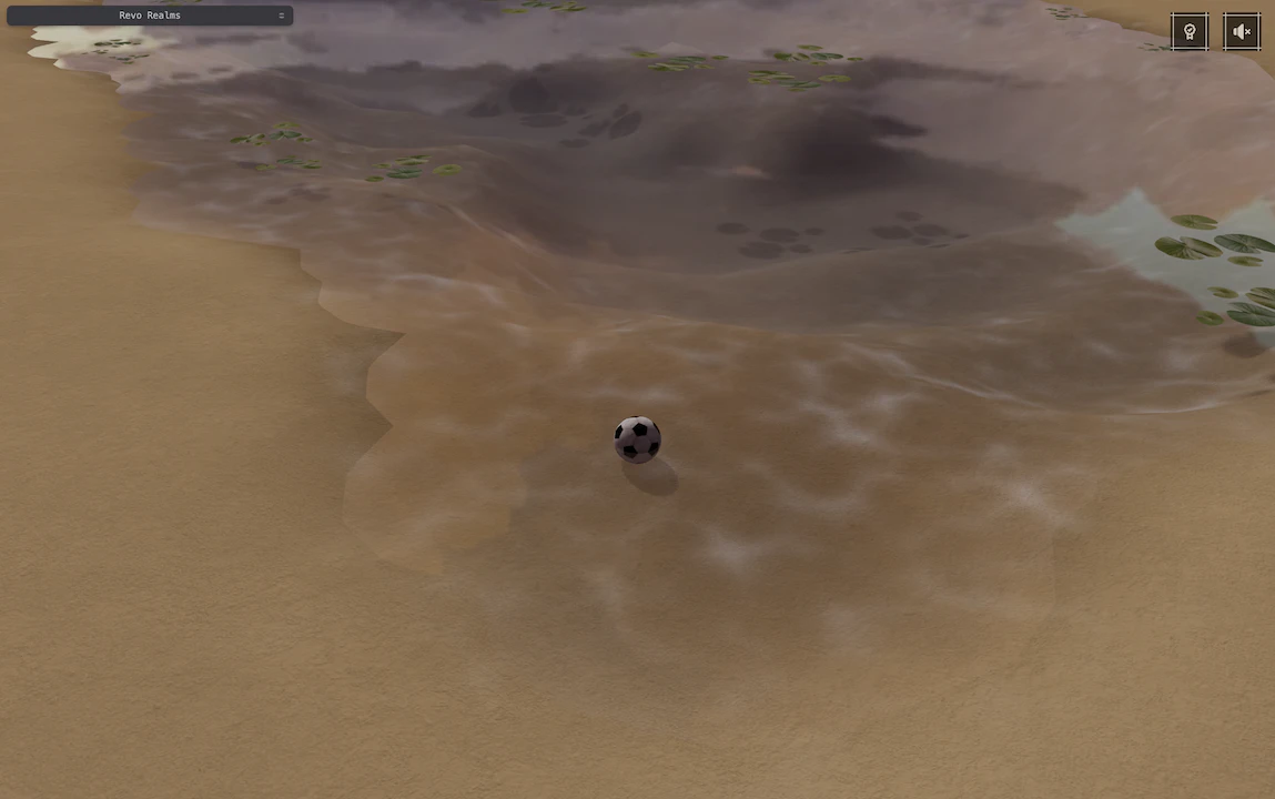
It wasn’t lush or my dream water yet, but I felt like I made a pretty important leap forward towards the lake I had
imagined.
The second iteration, with layered normal maps
The illusion still broke up close, if you walked into the water, it gave itself away. But from the right distance,
it was believable enough to move on. Revo flowed on without new waves for a while… until a post on X left me staring at the
screen, making me realize just how far I still had to go.
Chapter III: Beyond Ripples
After completing the second iteration, there was a period of “calm before the storm” :)
I enjoyed time differently, travelled a bit, got more into game engines and started tinkering with Godot. I learned the
basics and jumped right into building a small world, starting with a moving character of course and a super simple test
environment.
That done, I began digging more and more into shaders. Thinking I had access to much more power than with Three.js,
which I did but not solely because of Three.js, browsers tend to provide limited resources when it comes to graphics
APIs, so I decided to write a water shader, drawing inspiration from this post
I saw on X but also going all in with my creativity…still with an eye on performance.
As long as my MacBook Pro M2 wasn’t hot and my fans stayed silent, I was happy.
I started in Godot, then ported the shader to Revo (Three.js/TSL). Browsers limit graphics resources more than native
engines, but with some care you can still get plenty of headroom.
What followed wasn’t a single breakthrough but a stack of small pieces, each filling in part of the picture: normals to
shape the ripples, depth to give the water body, refraction to bend the world beneath, reflections and Fresnel to tie
the surface to the sky, highlights and glints to make it sparkle, Beer-Lambert absorption for color and weight, and a
simple opacity trick to give the final touch.
I could tell a whole story about each one, but I will do my best to trim things down for the sake of the article,
hopefully still providing valuable experience.
Surface Normals & Waves
The surface is always the starting point. No matter what tricks come later: depth falloff, absorption, reflections, if
the ripples don’t feel alive, the illusion collapses.
This version reused the normal maps from Chapter II, reduced the layering from three samples to two, but with a twist.
Instead of linearly interpolating between the two normals, like I did in my previous attempt via mix(n1, n2, 0.5), I
blended them using RNM (Reoriented Normal Mapping), which preserves directionality and fine detail by reorienting one
normal into the other’s space before combining.
If you’re curious, Self Shadow’s article is the gold
standard breakdown of RNM, UDN, and other variants.
The odd multipliers (1.37 and 0.73) aren’t completely random. If I’d picked clean ratios like 0.5 and 1.25,
the scrolls would eventually sync up and reveal a repeating pattern. Using awkward, almost-irrational numbers keeps the
two layers drifting forever without tiling in lockstep, a dirt-cheap way to break repetition.
Another small but important detail: I only scale the X and Y components of the tangent-space normal (tsn).
Those represent sideways tilt, the part that makes ripples catch the light. Scaling Z (the “outward” axis) would just
squash the surface flat and kill the contrast. It’s a subtle distinction, but it makes a big difference in how natural
the water feels.
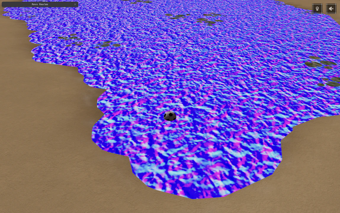
Tangent space normal as color
This is how the tsn should look if visualized as a color.
Of course, this is not what it’s for so let’s continue unraveling layers :)
Depth
Now that I had normals in place, I needed another “tool” before going all in with effects: depth.
Unfortunately, we cannot reason about depth as in the everyday sense of how far something sinks under
water, but rather in 3D graphics terms: how far each fragment is from the camera. Which is still super valuable.
In Three.js TSL, the entry point is viewportDepthTexture(uv). That gives you the value from the depth buffer, but it
isn’t in world units, it’s in clip space. After projection, X, Y, and Z all get squeezed into a normalized cube (NDC,
or Normalized Device Coordinates).
Here’s where it gets tricky: different APIs disagree on the Z range. WebGL/OpenGL use [-1..1], while WebGPU (along
with DirectX and Metal) use [0..1]. A tiny detail, but if you ignore it, the math falls apart.
I learned that the hard way: everything looked perfect in Chrome with WebGPU… until I opened Firefox (WebGL) and
my lake collapsed into nonsense.
From clip space to linear depth
The goal here is “linear” depth: the actual camera-space distance.
The usual way to recover linear depth is to take the fragment’s position in clip space and multiply it by the
inverse projection matrix. That brings it back into view space, and from there you can grab the Z value as the true
distance.
It works, but it felt like overkill, a full 4×4 matrix multiplication per fragment, just to get one number.
While digging around, I came across this excellent video that showed a
cleaner path. Since I only needed the Z, the math collapses: we can cherry-pick just two elements of the projection
matrix (I called them p3z and p2z) and compute it with a single division:
zlinear=zndc+p2zp3z
That shortcut spared me from pushing an entire inverse matrix into the shader and suddenly made depth cheap enough
to use everywhere.
Three.js doesn’t expose a reliable flag for WebGPU vs WebGL, even though it adapts internally, so I hooked up my own.
By checking navigator.gpu?.requestAdapter(), I set a uniform uIsWebGPU, and used that to drive whether I treat
depth as [0..1] or [-1..1].
Branching (if/else) would also work, but GPUs are happiest when every thread follows the same path; even a tiny
conditional can slow things down. Driving it with a uniform avoids that cost.
Another important detail: Three.js matrices are column-major (like GLSL). If you’re cross-checking OpenGL docs, which
often show row-major, the indices appear shifted. For example, what looks like row 3, col 2 in the docs is actually
.element(2).element(3) in Three.js. That mismatch tripped me until I realized it was just layout, not math.
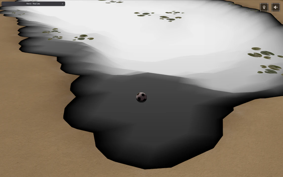
Here’s how the lake’s depth looks, scaled based on my world’s units (uDepthDistance):
Black means shallower, white means deeper
Depth was one of those invisible victories. At this point, I wasn’t even using it for anything fancy yet, but I knew
it was going to be a cornerstone for multiple effects. It drives how strong refraction bends the background, how quickly
light is absorbed with distance, even how the surface should fade near the shoreline. Without depth, all of those are
blind guesses.
Refraction
With depth in place, I could finally put it to work. The first effect I tackled was refraction, the way water bends
the world behind it.
Look into a shallow lake and the pebbles below look sharp, step deeper and everything starts to wobble and drift, as
if the world itself bends. That’s refraction: light changing direction when it crosses from air into water.
In the shader, I faked it by offsetting the screen texture with ripple normals. The trick is simple: take the
tangent-space normal’s X/Y tilt (not Z), scale by depth, and distort screenUV.
In TSL, viewportTexture(uv) is basically a live snapshot of the scene already rendered to the screen. Feed it
screenUV (ranging 0-1 across the viewport) and it hands you back the color at that pixel so far. Refraction is just
resampling that snapshot at slightly shifted UVs, so the background bends with the ripples.
//...// min and max refraction strength here are arbitraryconst distortionStrength = mix( uRefractionStrength, uRefractionStrength.mul(1.5), waterDepth,);const distortion = tsn.xy.mul(distortionStrength); // tangent tilt drives wobbleconst refractedScreenUv = screenUV.add(distortion.mul(isUnderWater));//...
Now that I had my refractedScreenUv if I directly used it to sample from the viewportTexture(uv) I’d make a big
mistake. I had the “pleasure” to get this wrong the first time, and that’s how I learned :)
Distortion can push UVs behind occluding geometry, pulling colors from places that shouldn’t be visible. Without a
fix, you end up with stretched pixels or peeking through geometry.
The solution is to re-sample depth using the distorted UV, and then use undistorted / distorted uv based on a validity
criterion, in my case depth (remember that depth does not refer to vertical depth of the lake but distance from view):
The isSafe mask ensures I only pull colors from fragments that actually exist in front of the camera. If the distorted
UV points behind geometry, I fall back to the original screenUV. A tiny guardrail, but it saves the effect from falling
apart.
Here you can see how big of a difference that makes (I slightly accentuated the refraction strength to make it more
obvious):
Without isSafe mask (edge bleeding)With isSafe mask (edges ok)
Refraction also scales with depth. In shallow spots, distortion stays subtle; deeper down, I let it grow stronger.
Without that, shallow water would wobble just as much as deep water, which feels wrong.
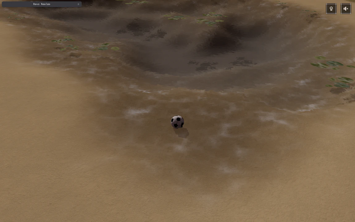
So far my water felt like a simple “painted” glass surface. This effect alone took it to a new level: now
it started interacting with the world around it, it finally had a body!
Refraction bending the scene beneath the lake
Of course, though, water doesn’t just bend the world, sometimes it mirrors it. That’s where reflections, and Fresnel,
come in.
Reflections, Fresnel & Viewing Angle
Refraction made the lake feel connected to the world beneath. The next step was tying the surface to the sky and its
surroundings.
I kept it simple: an environment cubemap blended using a Fresnel weight.
Reflections
First, I need to compute the reflection, which is simply a color for that specific fragment driven by the view
direction.
I built the view direction vector from the camera to each fragment, reflected it around the surface normal, and sampled
my sky cubemap:
This gave a convincing mirror-like color, but applied uniformly, it felt wrong. Water shouldn’t be equally reflective
when you look straight down and when you glance across the surface.
Skybox cubemap reflections
Fresnel (view-angle weighting)
That’s where Fresnel comes in. Dielectrics like water have a small head-on reflectance that ramps up toward the horizon.
I used Schlick’s approximation:
F(θ)=F0+(1−F0)(1−cosθ)5
Where:
F0 is the reflectivity at head-on, computed as F0≈((n−1)/(n+1))2. For water it’s around 0.02 (~2%).
cosθ is the dot between the surface normal and the view direction: the viewing angle.
The exponent 5 isn’t arbitrary, it’s Schlick’s trick, a balance between accuracy and efficiency. In reality,
Fresnel is derived from more complex equations involving polarization and material IOR, but this approximated form gets
close enough while being dirt cheap for real-time graphics.
With that, reflections fade in at grazing angles and fade out when looking down, where refraction and absorption
take over. It’s a small detail, but the kind your eye expects. Suddenly, the lake stops feeling like a static sticker
and starts behaving like a real surface.
One caveat: a cubemap has no parallax, so nearby objects don’t slide correctly in reflection.
It’s great for “a sense of sky” and distant scenery. Screen-space reflections (SSR) would be the next logical
step, but that’s a story for another time.
Fresnel: darker means less weight, lighter means more weight
Fresnel weighted reflections
This Fresnel-weighted reflection became one of the two main colors I blend at the end (the other is the “through-water”
color from absorption).
But water isn’t just a mirror, it eats light. Before I added the shiny bits, I needed the color to sink with thickness.
There goes Beer-Lambert.
Beer-Lambert: Depth-Based Absorption
Refraction bends the background; absorption decides how much of it survives the trip through water.
If you’ve ever looked into a lake, you know the water isn’t truly transparent. Shallow parts look almost clear, but as
depth increases, everything fades into blue or green. That fading isn’t just an artistic choice, it’s physics.
That’s exactly what Beer-Lambert describes.
In simple terms, it tells you how light gets absorbed as it travels through a medium.
The deeper it goes, the more it loses certain wavelengths. Water absorbs red light much faster than blue, which is why
oceans look blue-green instead of gray.
The equation looks like this:
T(λ)=e−σ(λ)d
λ → wavelength, the color of light (in my case screenColor); the equation works per wavelength,
but in code that simply means per RGB channel.
T(λ) → transmittance, how much light makes it through
σ(λ) → absorption coefficient, how strongly the medium “eats” each color channel
d → thickness, how far the light travels through water
In the shader, I keep it channel-wise and a slightly stylized:
Absorption here is art-directed. I pick my own coefficient per channel, something like vec3(0.35, 0.10, 0.08), so red
fades first, then green, and blue survives the longest. Scaling it with uAbsorptionScale lets me slide between a
clear alpine lake and a murky basin without touching the math.
For d (thickness), I mix waterDepth and waterDepthRefr based on the isSafe flag. When refraction gives me
a valid distorted UV, I use the refracted thickness; otherwise I fall back to the straight-through one. That keeps the
fade consistent with what’s actually visible.
Then I plug these into the Beer-Lambert formula to get transmittance, and blend between a teal-green tint of my choice
(uInscatterTint) and my λ (the screen color) based on that value. The deeper the water, the more light is
absorbed, shifting the mix from background color toward the tint.
TransmittanceWeighting teal tint based on transmittance
This was the point where everything started to connect: refraction bent the background, and Beer-Lambert gave it
weight and color as it sank into depth.
With that foundation in place, I could finally move on to the bright part: highlights and sun glints, and have
them sit in a scene that finally behaved like water.
Sun Glints
With absorption in place, the lake finally had body and depth, but it still missed that last bit of magic: the bright
sparkles that catch your eye.
Those flashes aren’t random; they’re sunlight reflecting off micro-ripples at just the right angle.
In shader terms, that’s just specular reflection, shaped by how tightly aligned the light, surface, and viewer are.
I already had my tangent-space normal, so I used it to craft a new world-space one specifically for highlights, letting
me tweak how tight or spread the sparkles should be.
Using the same normal for everything makes it physically more accurate but in all honesty it didn’t feel right visually.
A smaller scale made the reflections nice and visible and the surface calmer, like a lake should be, but highlights
became dull and condensed more and more into a white circle. A higher scale on the other hand had the opposite effect:
reflections became unrecognizable, but the sun glints looked beautiful.
This trades physical accuracy for a better look.
With the same normal as for everythingUsing a dedicated normal with a different scale
I had this idea during a late night gaming session, out of nowhere, while enjoying the marvelous environment of Ghost
of Tsushima. Highly recommended, the art direction is absolutely mind-blowing :)
Then, I reflected the sunlight direction around that adjusted normal, checking how well it aligned with the camera:
The result? The surface finally came alive: small, sharp bursts of light dancing with every ripple, fading naturally
with depth and angle.
It’s one of those touches that doesn’t need to be scientifically perfect; it just needs to feel right.
And now, with reflection, refraction, absorption, and glints all in place, the water finally looked believable,
not perfect, but grounded, like it belonged in the world instead of floating on top of it.
Opacity
The last piece was making the water fade naturally at the edges.
Even with absorption and refraction, shallow areas still looked too abrupt, like a hard line where water met land.
That’s where depth-based opacity came in.
Using the same waterThickness I’d computed earlier, I faded the surface smoothly from clear at the shore to opaque
as depth increased:
It’s a tiny touch, but it makes a huge difference. The shoreline blends softly, and the transition from shallow to deep
water finally feels natural.
I also experimented with another fade, one based on distance from the camera rather than depth. It wasn’t physically
accurate, but it worked as an artistic control: useful for tweaking underwater visibility when the player is submerged.
I ended up keeping it optional, just a creative knob to turn when I wanted more mood or clarity underwater.
In the final version, though, depth alone was enough. It handled the fade beautifully and kept the water looking
believable without extra tricks.
Outcome
Piece by piece, the shader came together.
The normals shaped the ripples.
Depth gave the water body.
Refraction bent the world beneath it.
Reflections and Fresnel tied it to the sky.
Highlights and glints added the sparkle.
Beer-Lambert absorption gave it color and weight.
And finally, depth-based opacity softened the shoreline, grounding the water in the scene.
Each part was “simple” on its own, but together they built something cohesive, something that finally matched what I had
in mind from the start.
This is the moment the lake stopped being an effect and became part of the world.
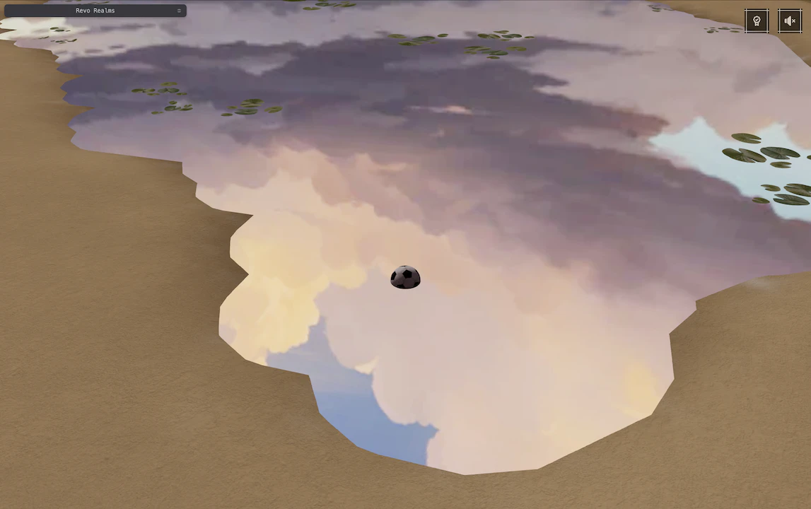
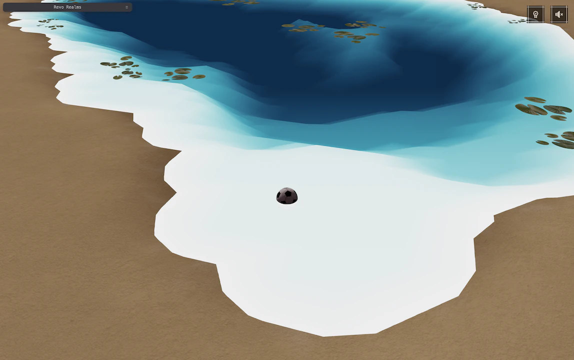
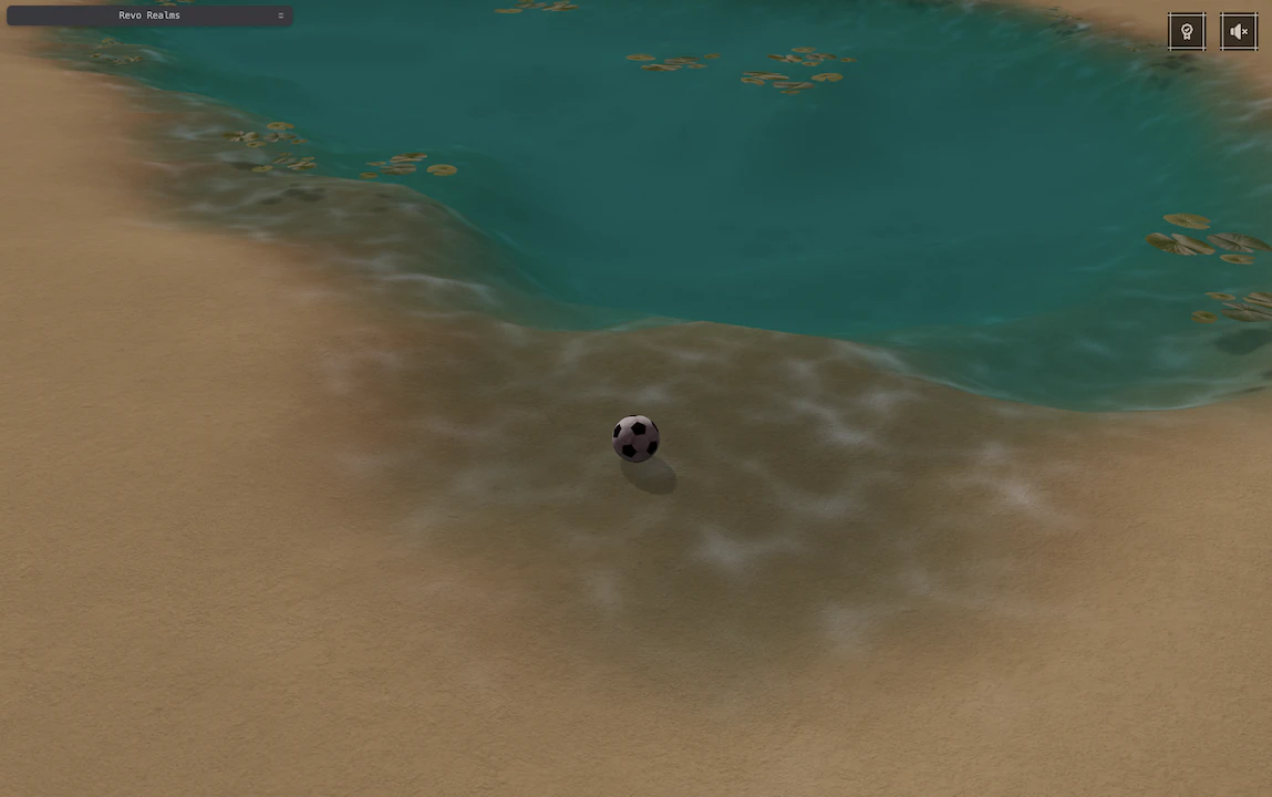
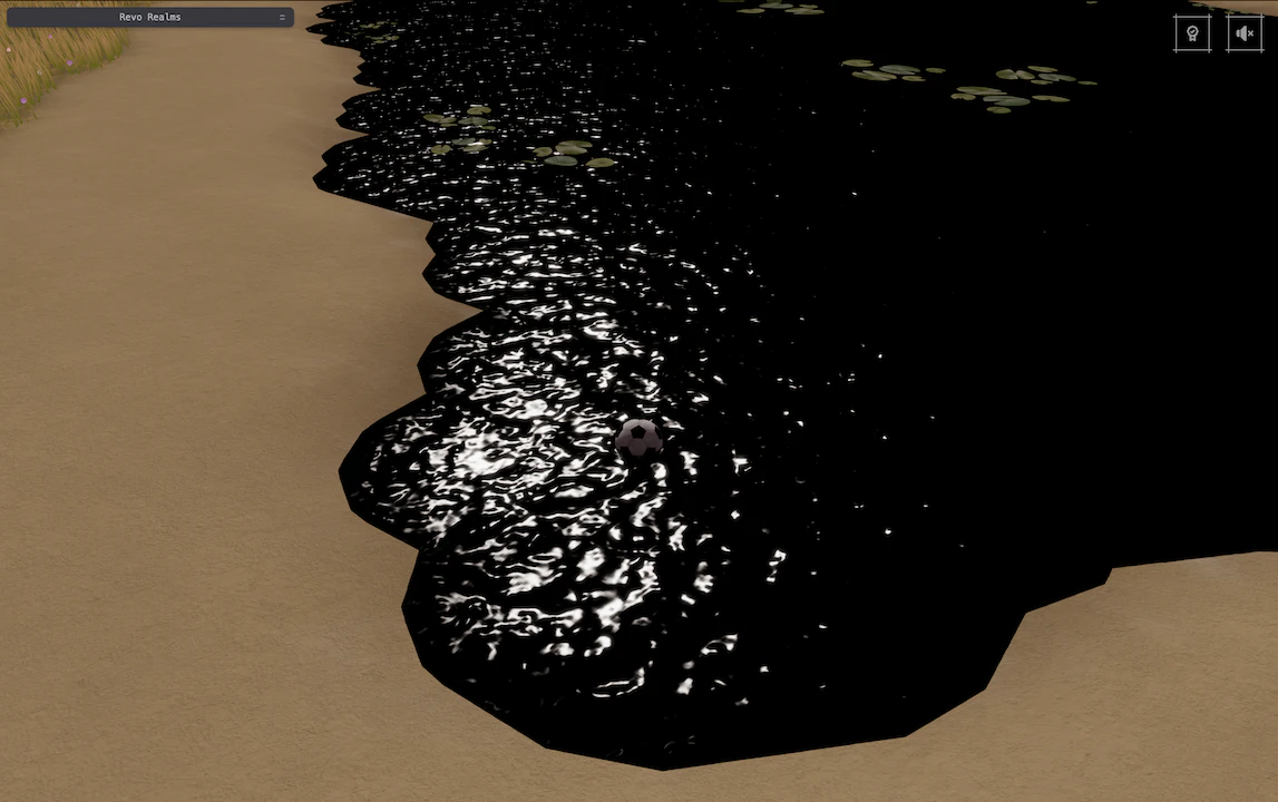
Here’s how it all came together:
The third iteration, refraction, reflections, absorption, and glints all
working together
Wrapping Up
I’m not completely sold on this water yet, but I’m really happy with the direction it’s taking. More importantly, I now
have enough controls to experiment with different moods without touching the shader’s core.
There are still plenty of ways to push it further: screen-space reflections, dynamic ripples reacting to movement,
buoyancy to make objects float naturally… maybe I’ll explore those in the future.
For now, I’ll leave it here: a shader that taught me a lot, gave me countless hours of fun, and stands as my humble
take on water in real-time graphics.
If you’re curious to dig into the full code, you can find the shader here.
I hope reading this journey was as valuable to you, as writing (and debugging) it was for me :)
Explore more
A few videos that inspired or complemented this exploration:

'/%3e%3cpath%20d='M80%2024H176L142%2058H46L80%2024Z'%20fill='url(%23paint1_radial_9_141)'/%3e%3cpath%20d='M142%2057.9998L176%2024V120L142%20154V57.9998Z'%20fill='url(%23paint2_radial_9_141)'/%3e%3cpath%20d='M45.5063%2058.9205C45.8968%2059.311%2046.53%2059.311%2046.9205%2058.9205C47.311%2058.53%2047.311%2057.8968%2046.9205%2057.5063L46.2134%2058.2134L45.5063%2058.9205ZM25.0002%2036.0002C24.4479%2036.0002%2024.0002%2036.4479%2024.0002%2037.0002L24.0002%2046.0002C24.0002%2046.5525%2024.4479%2047.0002%2025.0002%2047.0002C25.5525%2047.0002%2026.0002%2046.5525%2026.0002%2046.0002V38.0002H34.0002C34.5525%2038.0002%2035.0002%2037.5525%2035.0002%2037.0002C35.0002%2036.4479%2034.5525%2036.0002%2034.0002%2036.0002H25.0002ZM46.2134%2058.2134L46.9205%2057.5063L25.7073%2036.2931L25.0002%2037.0002L24.2931%2037.7073L45.5063%2058.9205L46.2134%2058.2134Z'%20fill='%23DB0000'/%3e%3cpath%20d='M46.9205%20154.707C47.311%20154.317%2047.311%20153.683%2046.9205%20153.293C46.53%20152.902%2045.8968%20152.902%2045.5063%20153.293L46.2134%20154L46.9205%20154.707ZM24.0002%20175.213C24.0002%20175.765%2024.4479%20176.213%2025.0002%20176.213H34.0002C34.5525%20176.213%2035.0002%20175.765%2035.0002%20175.213C35.0002%20174.661%2034.5525%20174.213%2034.0002%20174.213H26.0002V166.213C26.0002%20165.661%2025.5525%20165.213%2025.0002%20165.213C24.4479%20165.213%2024.0002%20165.661%2024.0002%20166.213L24.0002%20175.213ZM46.2134%20154L45.5063%20153.293L24.2931%20174.506L25.0002%20175.213L25.7073%20175.92L46.9205%20154.707L46.2134%20154Z'%20fill='%23DB0000'/%3e%3cpath%20d='M141.293%2057.5063C140.902%2057.8968%20140.902%2058.53%20141.293%2058.9205C141.683%2059.311%20142.317%2059.311%20142.707%2058.9205L142%2058.2134L141.293%2057.5063ZM164.213%2037.0002C164.213%2036.4479%20163.765%2036.0002%20163.213%2036.0002H154.213C153.661%2036.0002%20153.213%2036.4479%20153.213%2037.0002C153.213%2037.5525%20153.661%2038.0002%20154.213%2038.0002H162.213V46.0002C162.213%2046.5525%20162.661%2047.0002%20163.213%2047.0002C163.765%2047.0002%20164.213%2046.5525%20164.213%2046.0002V37.0002ZM142%2058.2134L142.707%2058.9205L163.92%2037.7073L163.213%2037.0002L162.506%2036.2931L141.293%2057.5063L142%2058.2134Z'%20fill='%23DB0000'/%3e%3cpath%20d='M142.707%20153.293C142.317%20152.902%20141.683%20152.902%20141.293%20153.293C140.902%20153.683%20140.902%20154.317%20141.293%20154.707L142%20154L142.707%20153.293ZM163.213%20176.213C163.765%20176.213%20164.213%20175.765%20164.213%20175.213V166.213C164.213%20165.661%20163.765%20165.213%20163.213%20165.213C162.661%20165.213%20162.213%20165.661%20162.213%20166.213V174.213H154.213C153.661%20174.213%20153.213%20174.661%20153.213%20175.213C153.213%20175.765%20153.661%20176.213%20154.213%20176.213H163.213ZM142%20154L141.293%20154.707L162.506%20175.92L163.213%20175.213L163.92%20174.506L142.707%20153.293L142%20154Z'%20fill='%23DB0000'/%3e%3cdefs%3e%3cradialGradient%20id='paint0_radial_9_141'%20cx='0'%20cy='0'%20r='1'%20gradientUnits='userSpaceOnUse'%20gradientTransform='translate(94%20106)%20rotate(180)%20scale(48)'%3e%3cstop%20stop-color='%2390BCB4'/%3e%3cstop%20offset='1'%20stop-color='%23CADDDA'/%3e%3c/radialGradient%3e%3cradialGradient%20id='paint1_radial_9_141'%20cx='0'%20cy='0'%20r='1'%20gradientUnits='userSpaceOnUse'%20gradientTransform='translate(111%2041)%20rotate(180)%20scale(65%2017)'%3e%3cstop%20stop-color='%2390BCB4'/%3e%3cstop%20offset='1'%20stop-color='%23CADDDA'/%3e%3c/radialGradient%3e%3cradialGradient%20id='paint2_radial_9_141'%20cx='0'%20cy='0'%20r='1'%20gradientUnits='userSpaceOnUse'%20gradientTransform='translate(159%2088.9999)%20rotate(180)%20scale(17%2064.9999)'%3e%3cstop%20stop-color='%2390BCB4'/%3e%3cstop%20offset='1'%20stop-color='%23CADDDA'/%3e%3c/radialGradient%3e%3c/defs%3e%3c/svg%3e)
'%20fill='%23D6E9ED'/%3e%3crect%20width='250.659'%20height='41.6404'%20transform='matrix(0.866044%20-0.499967%200.866044%200.499967%2092.6805%20318.321)'%20fill='%23688700'/%3e%3crect%20width='61.2359'%20height='61.2359'%20transform='matrix(0.866044%20-0.499967%200.866044%200.499967%2086.6805%20262.616)'%20fill='%23FF0000'/%3e%3ccircle%20cx='46.9475'%20cy='46.9475'%20r='46.9475'%20transform='matrix(0.866044%20-0.499967%200.866044%200.499967%2092.6805%20217.945)'%20fill='%232158C7'/%3e%3cline%20x1='127.491'%20y1='199.497'%20x2='128.497'%20y2='373.497'%20stroke='gray'%20stroke-linecap='round'%20stroke-dasharray='5%205'/%3e%3cline%20x1='0.502849'%20y1='126.497'%20x2='1.49713'%20y2='300.497'%20stroke='gray'%20stroke-linecap='round'%20stroke-dasharray='5%205'/%3e%3cline%20x1='217.503'%20y1='1.49712'%20x2='218.497'%20y2='174.497'%20stroke='gray'%20stroke-linecap='round'%20stroke-dasharray='5%205'/%3e%3crect%20width='250.659'%20height='146.966'%20transform='matrix(0.866044%20-0.499967%200.866044%200.499967%200%20125.321)'%20fill='%23D6E9ED'/%3e%3crect%20width='250.659'%20height='41.6404'%20transform='matrix(0.866044%20-0.499967%200.866044%200.499967%2091.6805%20178.088)'%20fill='%23688700'/%3e%3crect%20width='61.2359'%20height='61.2359'%20transform='matrix(0.866044%20-0.499967%200.866044%200.499967%2085.6805%20140.383)'%20fill='%23FF0000'/%3e%3ccircle%20cx='46.9475'%20cy='46.9475'%20r='46.9475'%20transform='matrix(0.866044%20-0.499967%200.866044%200.499967%2091.6805%20118.712)'%20fill='%232158C7'/%3e%3crect%20x='0.866044'%20width='249.659'%20height='145.966'%20transform='matrix(0.866044%20-0.499967%200.866044%200.499967%200.116012%20125.754)'%20stroke='black'/%3e%3crect%20x='0.433022'%20width='7.66479'%20height='7.66479'%20transform='matrix(0.866044%20-0.499967%200.866044%200.499967%20163.058%20143.299)'%20fill='%232158C7'%20stroke='black'%20stroke-width='0.5'%20stroke-linejoin='bevel'/%3e%3crect%20x='0.433022'%20width='7.66479'%20height='7.66479'%20transform='matrix(0.866044%20-0.499967%200.866044%200.499967%20163.058%20242.299)'%20fill='%232158C7'%20stroke='black'%20stroke-width='0.5'%20stroke-linejoin='bevel'/%3e%3crect%20x='0.433022'%20width='7.66479'%20height='7.66479'%20transform='matrix(0.866044%20-0.499967%200.866044%200.499967%20163.058%20266.299)'%20fill='%23FF0000'%20stroke='black'%20stroke-width='0.5'%20stroke-linejoin='bevel'/%3e%3crect%20x='0.433022'%20width='7.66479'%20height='7.66479'%20transform='matrix(0.866044%20-0.499967%200.866044%200.499967%20163.058%20286.299)'%20fill='%23688700'%20stroke='black'%20stroke-width='0.5'%20stroke-linejoin='bevel'/%3e%3crect%20x='0.433022'%20width='7.66479'%20height='7.66479'%20transform='matrix(0.866044%20-0.499967%200.866044%200.499967%20163.058%20321.299)'%20fill='%23D6E9ED'%20stroke='black'%20stroke-width='0.5'%20stroke-linejoin='bevel'/%3e%3c/svg%3e)